Key Takeaways
Registration marks give a cutter printed reference points for locating, rotating and scaling a cut path against the artwork.
One detected mark may establish an origin; additional marks can help a supported system correct skew, scale or distortion.
Marks do not repair a wrong cut file, missing bleed, severe print distortion or unstable material feeding.
Contrast, clear space, print scaling, laminate glare and sensor calibration all affect mark reading.
Test the exact printer, media, laminate, mark pattern and cutter configuration before approving production.
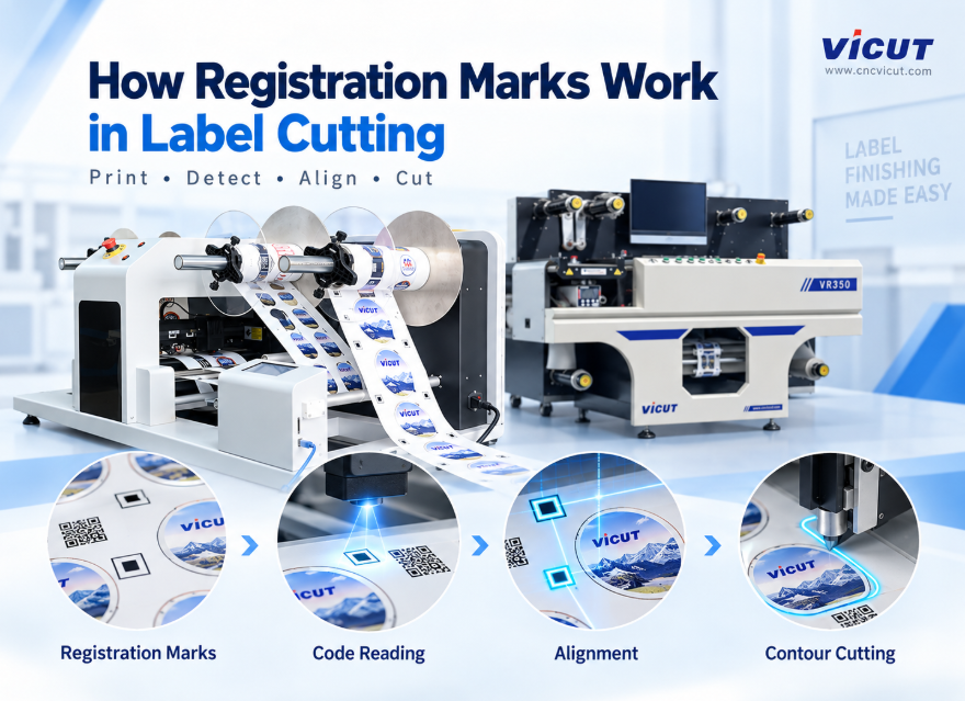
Registration marks are printed shapes that a label cutter’s optical sensor or camera reads before contour cutting. The control software compares their measured positions with the positions in the cut file, then shifts—and on supported systems rotates or scales—the cutting coordinates to fit the actual print. This is how print-and-cut equipment compensates for normal loading and printing variation without asking an operator to align every contour manually.
What Information Does a Registration Mark Provide?
A cutter does not “see” the label design as a person does. It receives vector paths and needs references that connect those paths to the physical web or sheet.
| Information | What the system learns | Why it matters |
|---|
| Origin | Where the job begins | Corrects overall X/Y position |
| Rotation or skew | Whether the print is angled | Rotates the cut path to match |
| Scale | Whether printed distances differ from the file | Adjusts supported axes |
| Job identity | Which cut file belongs to the print | Enables automated file retrieval on supported models |
The correction available depends on the machine, mark pattern and number of points detected. Do not assume that every sensor performs full two-axis scaling or local distortion correction. Ask the supplier what each mark does on the quoted model.
The Print-to-Cut Sequence
Create artwork and cut paths → generate supported marks → print at controlled scale → load the roll or sheet → detect marks → calculate compensation → cut → inspect
The print and cut files must come from the same layout. If marks are moved, cropped or regenerated independently, the cutter may read them successfully but still follow the wrong contour. “Fit to page” settings are a common source of trouble because they can resize the printed job while the cut file remains unchanged.
On a roll, a system may read marks for each job, repeat or panel. More frequent references can limit accumulated error, but they also use material and scanning time. On sheets, corner or edge marks usually establish the position of each loaded sheet. The correct pattern is software- and model-specific.
Sensor, Camera and Code Reading Are Different
An optical mark sensor normally looks for a defined contrast transition or printed target. A camera can capture a larger field and may identify different shapes or codes. A barcode or QR code can tell supported software which job to load, while separate marks still provide geometric alignment.
VICUT’s VR30 roll label cutter documents automatic contour cutting from generated registration marks. The VR350 multi-blade label cutter documents electric-eye and CCD functions, including coded job changes. These examples are model-specific; they do not make every VICUT cutter’s registration workflow identical.
Why Registration Marks Fail to Read
| Symptom | Check first | Likely category |
|---|
| Cutter cannot find the first mark | Loading orientation, start position, mark type | Setup mismatch |
| Mark is found intermittently | Contrast, glare, contamination, wrinkles | Optical condition |
| Entire contour is shifted equally | Sensor-to-tool offset, origin, file pairing | Calibration or file |
| Error increases along the job | Print scale, web tracking, panel strategy | Scaling or feeding |
| One material fails but another works | Surface color, reflectivity or laminate | Material-specific reading |
Keep the mark’s clear zone free of artwork, cut lines, dust and damage. Glossy laminate can reflect the sensor’s light differently from an unlaminated print. Dark, transparent or metallic constructions may also need a different validated method. Use the machine’s documented sensor adjustment rather than covering marks or changing their shape without approval.
Registration Cannot Fix Every Error
Registration can compensate only for variation the system measures and is designed to correct. It cannot recreate bleed, repair a contour exported at the wrong size, restore a missing mark or make a wandering web mechanically straight. Severe non-linear print distortion may remain even when all reference marks are detected.
Separate three questions during diagnosis:
Is the artwork and cut-path geometry correct?
Did the printer reproduce the mark spacing and design scale correctly?
Can the cutter detect the marks and transport the material consistently?
Changing blade pressure will not solve a registration error. Likewise, changing sensor sensitivity will not fix a mismatched cut file.
How to Test Registration Accuracy
Use a file containing small circles, rectangles, long repeats and contours close to the artwork edge. Print several repeats across and along the web. Number them before cutting, then measure the offset at the leading, middle and trailing positions.
Repeat the test on the normal paper or film, with the production ink or toner and any laminate applied in the intended sequence. Test after a stop and restart. Record mark-detection failures separately from cut-position errors because they have different causes.
For sheet workflows, the VICUT guide to autofeed sheet sizes and materials explains why curl, coating and transparency must be tested with registration. For roll workflows, start with the VICUT roll label cutting range and confirm the exact sensor and software supplied.
Questions to Ask Before Buying
Which mark shapes and colors are supported?
How many points are read, and what corrections do they enable?
Can the system read laminated, clear, dark or reflective jobs?
Does it read a code for automatic job retrieval or only alignment marks?
How are sensor-to-tool offset and media-specific calibration stored?
What happens when a mark is missed during an unattended run?
Send VICUT the printer output, cut file and representative materials. A model-specific test is more useful than a general accuracy claim because registration is a complete print, media, software, sensor and feeding workflow.
FAQ
Do registration marks control cutting depth?
No. They align position. Blade exposure, force, passes and material construction control cut depth.
Are more registration marks always better?
Not automatically. Additional points may enable more correction, but they also use space and scanning time. Use the pattern specified for the machine and job.
Why do marks work before lamination but fail afterward?
The laminate may change contrast or create glare, and the web may also stretch or skew during lamination. Test marks after the intended finishing sequence.
Can a camera read a QR code instead of registration marks?
A code may identify the job, but geometric alignment still requires supported reference information. Confirm the exact workflow for the quoted model.
 vicutcnc@cncvicut.com